Web Energy Logger
- - What is the WEL?
- - How does it work?
- - Purchase Online
- - User Map / Info.
- - OurCoolHouse
Tech Support
WEL Logging (Users)
WEL Display (Users)
Installing the legacy encapsulated temperature sensors (with green wires).
These were the first inexpensive 1-wire sensors I could find. They aren't sold anymore,
but some people may still have some in their tool-kits
If your sensors have longer black & red wires, go to this page.
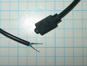 |
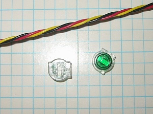
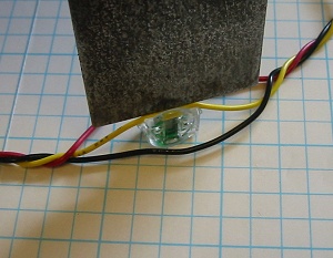
This is how the sensor comes to you. The two short wires look identical but they are NOT! I start by just trimming the exposed copper wire off the ends to make the assembly easier to work with. Since we are going to us a crimp splice on the wires, we don't need any exposed copper. |
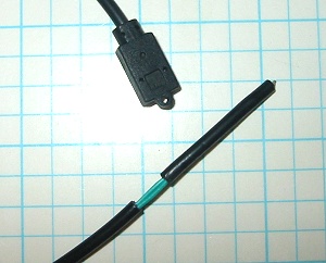 |
The first step is to expose some more of the green wire to make the connection possible. I measure back about 1 1/4" and snip the black outer layer. This enables me to slide it off to expose the green wires. Be careful not to snip too deep, otherwise you will damage the insulation on the inner wire. |
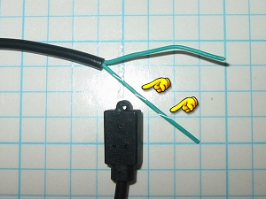 |
After exposing the green wires, you need to locate the one with the incredibly faint white line on it. I find the best way to do this is to spin the wire a bit and the while line will show up as a faint spiral. This striped wire is the 1-Wire signal wire. |
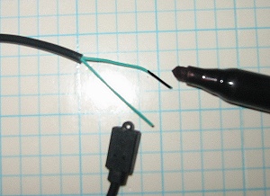 |
After locating the signal wire, mark the OTHER wire with a black permanent marker. This wire will end up connected to the Black bus wire. OK, now the sensor is ready to install. |
 |
Next let's look at the bus wire itself. Since the new sensors
have thinner wire, you should have received two small telecom splices,
and your bus wire should be 24AWG. The wire I supply has thicker
insulation than standard Cat5e network wire, so it's a bit more robust
for making tap splices. Regular Cat5(e) wire is great for long runs where you are just connecting at the ends. |
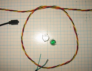 |
I like to add a small service loop at each location that I intend to install a sensor. This gives me some extra wiggle room in case I don't get the wires placed perfectly, or if (heaven forbid) I ever need to cut the wires to do some additional cable runs. A 6" diameter loop is plenty. |
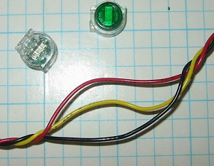 |
At the point where you are going to place the splice, you need to separate the three bus wires. Just grab the bus with your fingers about 2" apart and untwist the wires. If you are just adding a temperature sensor, you only need to get access to the Black and Yellow wires. |
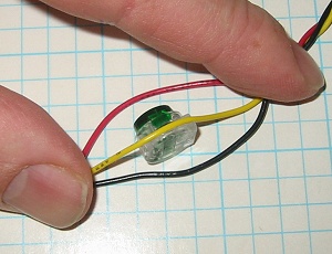 |
Since my bus wire has larger insulation than normal telecom wire, placing the
splices is a bit tricky, but it ends up being an advantage, because once
the splices are on the bus, they stay in place so it's easier to add the
sensor wires later. Identify the side of the splice that has the full slot on it (the other side just has an opening at one end.) Lay the wire into the slot and press the whole thing against a flat surface. In the picture my fingers are holding the wire against the surface, which in holding the splice in place. |
 |
Next, take a thin flat tool (a putty knife is perfect) and press the
wire firmly into the slot. You will hear a snap, and the wire will
slide through the slot, and into the body of the crimp. Repeat this process for the other wire. It helps if you align both crimps with their green sides facing the same way. |
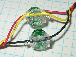 |
Here you see both crimps installed. Notice the the wires pass
straight through the crimps without any bends. This is important
to ensure a good electrical connection. Also note that some clear
gel is oozing out of the crimp. This is a water barrier and will
help with the long term quality of the connection.
As I mentioned before, the crimps are now held firmly on the wire, so if you wanted, you could install ALL the crimps for all the sensors at once, and then go back and connect/identify the actual sensors one at a time. |
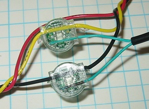 |
Now it just remains to push the sensor wires into the holes at the
side of each crimp. Notice that the green wire
with the black pen mark is connected to the Black Ground wire and the white
striped wire is connected to the Yellow Bus wire. Make sure you push the wires all the way in so they get the full double contact when crimped. |
 |
Complete the connection by squeezing in the green disk on one side. You can use regular pliers or grips to do this, but I prefer to use a special tool designed just for this purpose. The tool shown here is from Pro's Kit and it is model number PK-CT006 It has matching flat surfaces to spread the forces over the entire disk, and it will only close far enough to complete the crimp, you cannot over clamp the plastic crimp. Squeeze both crimps until the green disk is pressed flush. Make sure the sensor wire doesn't slide out while you are crimping. |
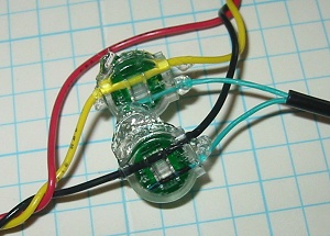 |
Here
is the completed connection. Notice that the clear gel has filled
all the inner voids and that both teeth of each metal crimp are engaging
their wire.
After connecting each sensor, don't forget to scan the 1-Wire bus using the WEL and assign a name to the new sensor. |
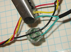
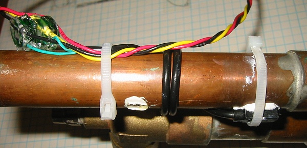
Here you can see a final installation just prior to being insulated.
The service loop of the Bus wire passes across the pipe to be measured.
One small tie-wrap (left) is used to hold the bus and the sensor cable
against the pipe for maximum strength. Then the black sensor cable
is wrapped around the pipe (to improve the thermal coupling) and finally
the sensor itself is strapped to the pipe (lower right). You can
also see that white thermal grease has been added to the sensor to
improve its thermal coupling with the pipe. This configuration
will provide an accurate and responsive thermal measurements with
excellent durability over time. Cover the whole assembly with
insulation.
 |
|